Thursday, April 11, 2013

"Hedwig"-USB Powered Owl Head

AttachmentSize
HedvigPdes.zip2.18 KB
This one I made for my future sister-in-law for Christmas. (She's a big Harry Potter fan.) It uses two CdS cells, Two AT Tiny 45s, two blue high-output LEDs and a single servo. The body is made from extruded PVC (Sintra/Komatex/etc.) and a PVC pipe joiner. I used an Arduino as ISP to program the AVRs. This project served as a demonstration of how sometimes it's actually easier to use microprocessors to achieve results normally associated with BEAM robotics. If you think about it, the component count is about half what you'd have for a bicore head and the number of solder joints is less than half, with the added benefit of not having to hack the servo. Also, trying to get a Schmidt Trigger cascade to function is such a crapshoot-you can go through a roll of chips and maybe have one work. Also, trying to get a 555 or a 741 to "breath" is more challenging than the available schema would predict.
Update-Pi day, 2013
I'm not just doing this for attention, I swear. There are a few other LMR members now interested in the ATTinies, so as a resource I thought I'd add some more goodies. For starters, here's the schematic:

The servo is just a regular old cheap eBay transluscent blue 9g (not even an official "Tower Pro."
I've also added the sketches. Remember this is Arduino as ISP with the HLT cores. The ATTinies are as far as I'm concerned not a great choice for servo control or small robots. If you want to work with an 8pin DIP micro, in my experience the PICAxes 08m(2)s are a better choice. The Tinies have their place, but they just don't have good enough timing (at least not through Arduino as ISP-I've never tried another AVR programmer or a crystal regulated ATTiny for example.) The servo control I acheived on Hedvig by all rights shouldn't work, and possibly was a fluke of combination of one individual chip and one individual servo just happening to be on the same "wavelength" as it were. I just found one PWM frequency that forced it all the way right, one all the way left and one that (unbelievably) centered it up.
Read more »

RoverBee One

AttachmentSize
RoverBeeOne_leftside.jpg2.15 MB

Second robot ever built using the following:
- Erector set for chassis.
- Arduino Uno
- Arduino Motor Shield r3
- HC-SR04 Distance Sensor
- Tamiya Twin Motor gearbox
- Radio Shack 9V connector (270-0324) & Plug (274-1569) to power the Uno
- Radio Shack 4-AA battery compartment (270-0391)

I wanted to build a second robot after building the Popular Mechanics Build Your First Robot. I used the Clusterbot as influence since I had an Erector set to use and more parts from the first build. This took longer than I wanted due to poor soldering, weak connectors on the FA-130 motors, and design decisions since it was a scratch build for the most part. I am calling this completed, though, I need to do minor tweaking to the code base.

Both robots:
http://imageshack.us/a/img96/127/roverbees.jpg
Read more »

BTBotControl – IPCam Bot

MasterFeatureGraphic800w
BTBotControl is an Android application that allows you to remotely control a micro controller-based robot using Bluetooth (i.e. Arduino).  It also allows you to (optionally) view a video stream from an IPCamera mounted to your robot.  This could be any type wireless IP camera or phone that has the ability to broadcast a video stream/images to the web.  Example Foscam, Ai-Cam etc.

Some of the features of BTBotControl:
  • Can use Joystick via finger movement, or the orientation sensor on your device.  (default is Joystick mode).
  • Supports 8 individual commands via Command Buttons.   4 on by default. 4 more can be turned on in the Settings section.
  • Sends the x/y coordinates as positive and negative integers based on 4 quadrants of the joystick.   Data is sent via Bluetooth and can be parsed to set both direction and velocity.  (sample code below)
  • Coordinates are generated as X+/- and Y +/-. These are packaged and sent in the following format sX=val,Y=vale  i.e. sX=75,Y=-55e  where ‘s’ indicates the start and ‘e’ indicates the end.
  • Command button values are packaged and sent in the following format: sC=[val]e  i.e. sC=2e  where ‘s’ is the start,  ‘c’ indicates the a command button as pressed, ’2′ is the value and ‘e’ indicates the end.
  • Configurable Bluetooth packet send interval – used to set the speed (quantity) of packets sent.  Default of 200ms works well.
  • Shows video stream of IP Camera mounted to robot. (see FAQ)
  • Configurable camera URLs. Remembers last camera connection for easy re-connect.
  • Configurable Bluetooth connections.  Remember last Bluetooth connection for easy re-connect.
  • Sample Arduino Sketch provided (below).
  • Screen auto re-sizes for smaller phones.
  • Supports any micro controller that can parse Bluetooth data (bluetooth module required) (sample sketch below).
Note on Lite version:  The Lite version is a fully functional version.  However, Bluetooth data will be sent as ’9′s.  i.e. s9,9e and c9e which will provide you with enough to determine if this app is right for you.  If you like BT Bot Control, the Pro version has full functionality enabled with proper data, and can be yours for less than the price of a coffee.  Also, you won’t be pestered by that start-up message either!  We hope you agree that the features and functionality provided are well worth the pocket change. :)
Note on Bluetooth: The control distance is dependent on a number of factors including; your Bluetooth device range, battery power, obstacles etc.
Download BTBotControl here:

Get it on Google Play

If you have an feature requests, or suggestions,  please let me know.
Sample Sketch: IPCamBot Arduino Sketch
Note:  For this project, I used a Digispark (Arduino-based micro controller).  This sample sketch is targeted for a Digispark (ATTiny85), but was also tested on an Uno, so it should work for most Arduino’s.   If using an ATTiny, remove any Serial.Print statements. Also watch the size of the sketch as there are limitations on the ATTiny85.  
Here are some pictures of the bot (click to enlarge):
BTBotControlScreenArtweb
Read more »

IMR (Intelligent Mining robot)

AttachmentSize
Diamond.zip1.39 MB

Hello everyone,this is the miner robot,I have built for The Diamond mining challenge. This is the easiest possible solution I could think. Since I am just a newbie in this field, it was very hard for me to find a solution to this problem. I don't have high-tech tools to work with,so just tried to do what was possible using a few things.
Experience level :
1. First time working with track belts (actually bought one for this challenge).
2. Fourth Robot,first one being an obstacle avoider.
3. New to Infrared coding and decoding,learning from microM library.
4.Had two previous designs discarded.
5.Been Only 3 months till I've been a member of LMR. Before that I didn't know anything about robotics.
I am using -
1. transparent marbles as Diamonds
2. Sand and black marbles as dirt and stones.
The bot-
1.travells 3 meters from a place guided via IR signal (Can be made RF signals for larger and true bot).
2.Digs in dirt.
3.Sorts Diamonds and stones and stores the diamonds in the container,throws away stones.
4.Comes back with the diamond box guided by IR signal.
So,the bot looks like this

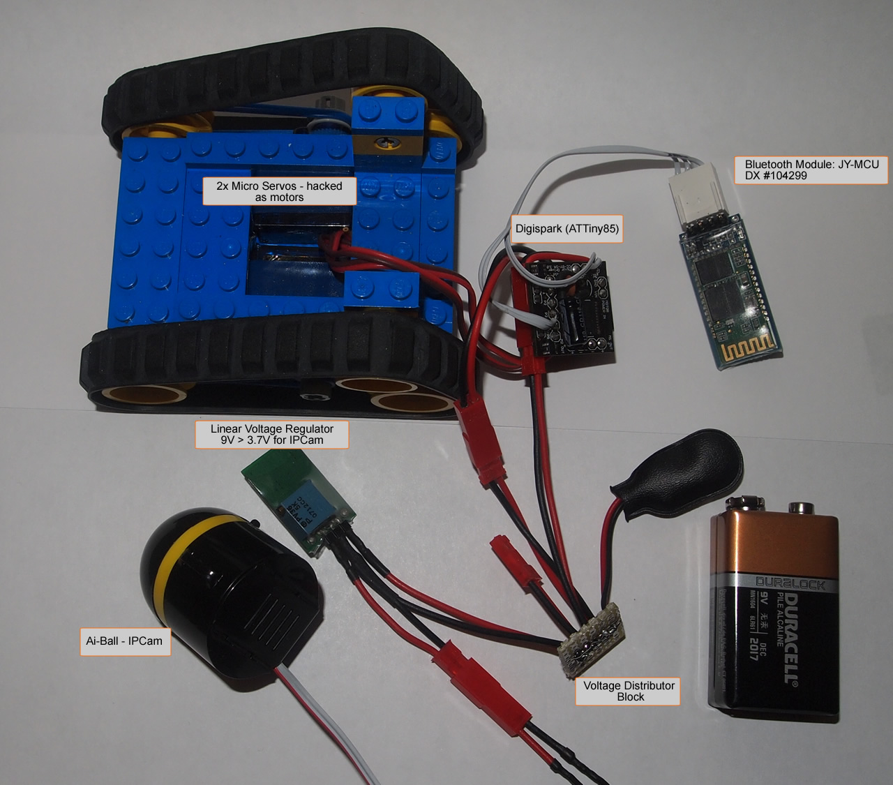
The claw on the front is home-made from metal wires. I used pliers to bend them,and used wood and paper to hold the pieces into proper place. There's a servo just under it to control the claw.

This is the first time I am working with Track belts.


The container for diamonds is just under the wooden "chassis."

The mechanism on the back side of the bot has a LDR and a High Power LED,between which a "diamond or stone" is inserted to check the transparency. The mechanism moves left and right, on both the sides,there are holes for the Diamonds/stones to fall. the hole on the side of the diamond has a container beneath it,while the one at the side of stone has none.( refer to the attachments and the video to understand better.)


I had a few previous designs too,in that I tried to use a conveyor belt,to replace the middle portion,which I was making at my home,but couldn't find enough time to complete it.


I had made another design too,but battery problem forced me to reject that design

Anyways,the bot uses micro magicians IR decoding library,to detect IR signals from a Sony remote and work accordingly. The robot is semi-autonomous. It is navigated via remote control,and does the mining work itself. I can also change the position of the claw (between REST and DOWN),making ti easier for the bot to control the mining process.
After the stones and the diamonds have been taken out of dirt,they are passed through the LDR and LED combo,to determine which one is diamond,and which one is rock.
The diagram is as follows.

The High Power LED can't be driven by the Atmega directly,so I'm using the TIP 122 to control it via the digital pin 9 (see above diagram).
Tools I have to work with,I cut the ply-wood with this saw. (This is the reason my bots don't look good,professional)


AND.......THIS is what I got from my crater.....:D :O :D :P

I actually have this in my home.


Problems:
1. IR signal does work over three meters,but sunlight tend to disrupt it.
2. The LDR sensor was not working properly under daylight conditions,until I changed a few codes.
3. The idea of this challenge as a whole is too complicated,I don't have the experience to tackle that,Still I've tried something.

Stay Update With : http://robot-parts.blogspot.com/
Read more »

Enviromentally Friendly Wild Thumper


Recently my company has been asked to demonstrate a robot that can perform an enviromentally friendly task. I only have about 1 month to complete the robot and I'm not sure what it will do yet. I decided to build a robot that could perform many different tasks and then it should just be a matter of programming it.


Construction:

As all the ideas I've had so far are outdoor activities I decided I had to use a Wild Thumper 6WD chassis.The ideas so fare are:
  • Water conservation on farms by mapping out a field using GPS and moister probe to determine when to water crops.
  • Collecting soil samples tagged with GPS locations to look for contamination near factories.
  • Planting seeds or saplings.
I've installed 2x 7.2V NiMh 5000mAh battery packs. A Wild Thumper high power switch on the back controls power to the robot. This switch can be remotely controlled using either a 3.3V or 5V logic signal making it possible for the robot to be turned on or off by a low power receiver.

I want this robot to be able to pick things up so i decided I wanted robot arms. I have put a 6DOF robot arm on a 6WD before but I wanted this arm to move more like a human arm so I modified a DAGU 6DOF robot arm to make it a 7DOF robot arm. I need to build a second arm.

The torso of the robot is made with 2 top decks from a 4WD Wild Thumper. The front section can be removed for easy maintenance. Inside the torso is a Spider controller which will control the two arms. A heavy duty servo shield allows the servos to be powered directly from the 7.2V batteries.

Behind the Spider controller is a second high power switch. This switch is controlled by D12 of the Spider controller and switches power to the arm servos. This allows the Spider to initialize the servo pins before the servos are powered up. This prevents random and sometimes violent twitching that can occur when servos are first powered.

By the time I added the second arm it was obvious that the front suspension could not handle the load. I had considered just adjusting the original suspension to full hardness but as the two arms are so heavy I decided to double the springs instead. I drilled extra holes to remount the cable in a new position.The entire robot is now about 6.1kg with the arms and torso being 2.5Kg.

The arms are made from 3mm thick aluminium and all the servos are metal gears. The gripper and wrist rotation servos are small and only rated at about 2.5Kg/cm each. The other servos are 13Kg/cm each except for the shoulder servos which are 40Kg/cm. Each arm has a span of 500mm from shoulder to claw tip.


Ultrasonic Eye:

Originally I tried mounting 4x HC-SR04 ultrasonic rangefinders on the chest of the robot to track objects within range of the arms but the field of detection for the ultrsound sensors is only about ±15° so it became obvious the sensors needed to move and track objects in range.
I have now added a pan / tilt assembly and made a simple head with the sensors mounted about 100mm (4 inches) apart. The first video shows my first attempt to track my hand movement. The readings from the sensors have a lot of noise which is made worse when the head moves so I need to experiment some more with noise filtering (currently I average the last 10 samples) and maybe some PID control. After spending half a day trying to improve the tracking I have left it where it is in the second video.
The big problem with the ultrasound is the relatively narrow detection range of the sensors. When an object is in range and detected by all 4 sensors then the difference in readings is very slight due to the 100mm difference in spacing of the sensors. As soon as the object gets too far to one side, The readings from one or more of the sensors change abruptly.


Follow Me:
this is a simple test of the I²C communications in this robot. Speed and direction are determined by the angle of the pan servo and the distance between the robot and an object. The robot attempts to turn and face the object while maintaning a certain distance.
The Spider controller is the I²C bus master and the Wild Thumper controller is the I²C bus slave. The master sends 5 bytes of information to the slave. These bytes are:
  1. acknowledgment of battery status
  2. left motor direction
  3. left motor speed
  4. right motor direction
  5. right motor speed
If the Wild Thumper controller does not receive these commands regularly (at least every 200mS) then it will assume a bad I²C connection and ramp the motors speeds down to 0.
The third video shows my second attempt at "follow me". The First attempt failed due to flat batteries. I need to find the right balance between responce to changing sensor inputs and ramping of motor speed. As I am using 75:1 gearboxes, ramping the motors speed is important. The high gear ratio means it is possible to break the metal gears by forcing the wheel to turn against the motor.
I've added a small switch that connects D11 to either Gnd or Vcc. The code uses the state of D11 input to enable / disable the "follow me" function.


Arms:
With Maker's Faire ShengZhen coming up fast I needed to get the arms working quickly. Video 4 shows some simple code running so that when an object is within 200mm to 500mm the arms will reach out towards it. This code only operates 4 of the 14 servos and is controlled by the tracking. Unfortunately, because the tracking is jittery the arms shake a bit as well.
Later I will try to write some simple "inverse kinematic" code for the arms.

Fr More Stay Update With : http://robot-parts.blogspot.com/
Read more »

Anbot - a vision based micro robot


Hello everyone!
I just joined LMR and sharing my current robot in progress, called Anbot. It's a vision based micro robot. Following is a bit of details.
The hardware will have:
  • Track based locomotion
  • Battery box (4x AAA)
  • SN754410 motor controller
  • PIC18F26K20 micro
  • MRF24J40MA Zigbee/wireless
  • JPEG camera
Offboard hardware will also include:
  • A Zigbee remote controller
  • A Zigbee Raspberry Pi gateway for connecting to home router
Features it will have:
  • Will be connected to home network and internet via the gateway
  • Can be controlled from the PC, Phone or iPad via internet. Camera can be turned on and off. Photo will be shown on PC/iPad.
  • Can send out JPEG image (VGA) continuously
  • Will have autonomous line following mode
  • Will have autonomous shape/direction following mode.
I'm maintaining this blog to show step by step progress: http://robot-parts.blogspot.co.uk/
I hope to make a good progress by this month. I appreciate your ideas, comments and suggestion.
Please let me know what do you think of this robot. Have a great time!
Thanks!
Read more »

Tuesday, April 9, 2013

Kaboodle Fashionable Funny Robot


The 2 images below was my first attempt at a robot using fritsl's guide. After my first attempt i felt ashamed of how flimsy and goofy the robot looked.
Picture_25.jpgPicture_27.jpg
 So I broke it apart and re-did it!
I decided to invest more time to make a custom chasis using the battery pack as the core as it is the most solid and non fragile component, then surrounding it in rubbery material (known to me as kaboodle) i bought at an art supplies store. I used 2 power supplies in this newer version, since fritsl wrote an excellent guide on it. http://letsmakerobots.com/node/75
 Picture_44_0.jpg
 Picture_45.jpg
 Picture_42.jpg
 Picture_50.jpg
The material is very easy to cut and glues together great with a glue gun. It's also pretty forgiving with mistakes. Plus, it allows you to temporarily mount stuff on it using needles or pins.
But since it bends, my wheel alignment was wonky. So i put a makeshft axle between the two motors (lower left). i also added a tail wheel as a 3rd contact point since those little black "dots" at the end of the motors wern't cutting it (lower right) the wheel part was originaly for RCairplanes.
http://www3.towerhobbies.com/cgi-bin/wti0001p?&I=LXMRK6&P=WR
Picture_59.jpg

Picture_60.jpg 
The head i fashioned out of the same material. Using one of the alphabet letters (letter "i"). Letter H would have been a better choice although it didnt come in black :(
Picture_61.jpg
 Picture_62.jpg
If your wondering about the foamy eyes, read more about why i did that here... http://letsmakerobots.com/node/1276
I also added a speaker so it boops and beeps like robots on tv! the beeps are based on sonar results.
Picture_56.jpg

The funny thing about buying stuff at an art supplies store is you get tempted to"accessorize" your project. Here I bought my friend some fashionable headwear for $1.50
Picture_63.jpg
Read more »

Visits

Flag Counter